Voyager 1 and 2
Spacecraft
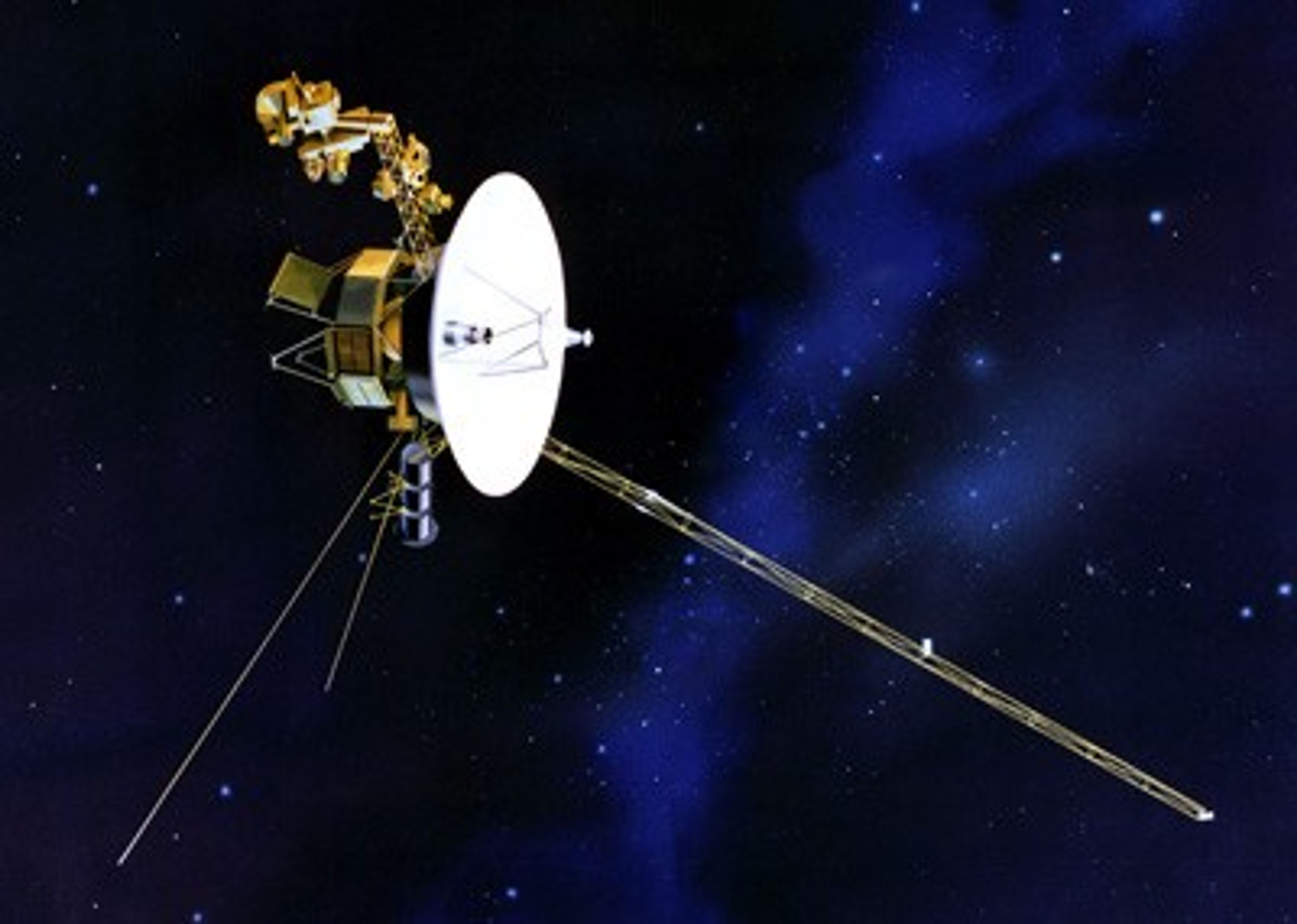
The Voyager spacecraft are identical twins. Both were designed to explore the outer planets in our solar system. They are now hurtling through the edge of interstellar space. Four of 11 science experiments remain active.
Spacecraft
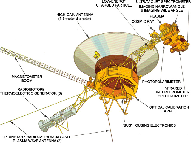
The identical Voyager spacecraft are three-axis stabilized systems that use celestial or gyro referenced attitude control to maintain pointing of the high-gain antennas toward Earth. The prime mission science payload consisted of 10 instruments (11 investigations including radio science).
The command computer subsystem (CCS) provides sequencing and control functions The CCS contains fixed routines such as command decoding and fault detection and corrective routines, antenna pointing information, and spacecraft sequencing information.
The Attitude and Articulation Control Subsystem (AACS) controls spacecraft orientation, maintains the pointing of the high gain antenna towards Earth, controls attitude maneuvers, and positions the scan platform.
Uplink communications is via S-band (16-bits/sec command rate) while an X-band transmitter provides downlink telemetry at 160 bits/sec normally and 1.4 kbps for playback of high-rate plasma wave data. All data are transmitted from and received at the spacecraft via the 3.7 meter high-gain antenna (HGA).
Electrical power is supplied by three radioisotope thermoelectric generators (RTGs). As the electrical power decreases, power loads on the spacecraft must be turned off in order to avoid having demand exceed supply. As loads are turned off, some spacecraft capabilities are eliminated.
The basic structure of the spacecraft is called the "bus," which carries the various engineering subsystems and scientific instruments. It is like a large ten-sided box, which can be seen in the Voyager diagram. The centerline of the bus is called the z-axis (and thus the High Gain Antenna) points to Earth. The spacecraft is designed to roll about this axis by firing small thrusters which are attached to the bus.
Each of the ten sides of the bus contains a compartment (a bay) that houses various electronic assemblies. Bay 1, for example, contains the radio transmitters. The bay are numbered 1 to 10 (numbered clockwise as seen from Earth).
The HGA transmits data to Earth on two frequency channels (the downlink). One, at about 8.4 gigahertz (8,400 million cycles per second), is the X-band channel and contains science and engineering data. For comparison, the FM radio band is centered around 100 megahertz. The X-band downlink science data rates are as high as 7.2 kilobits per second. The other channel, around 2.3 gigahertz, is in the S-band, and contains only engineering data on the health and state of the spacecraft at the low rate of 40 bits per second. S-band has not been used since the last planetary encounter.
The target plate is a flat rectangle of known color and brightness, fixed to the spacecraft so the instruments on the movable scan platform (cameras, infrared instrument, etc.) can point to a predictable target for calibration purposes.
Radioisotope Power System (RPS)
Status: As of 2023, the twin Voyagers' RTGs are in stable operation at 225 We.
Three radioisotope thermoelectric generator units (RTGs), electrically parallel-connected, are the central power sources for the mission module. Each RTG is made up of a radioisotope heat source, a thermoelectric converter, a gas pressure venting system, temperature transducers, connectors, a heat rejecting cylindrical container, and bracketry. The RTGs are mounted in tandem (end-to-end) on a deployable boom as part of the MM.
The heat source radioisotopic fuel is Plutonium-238 in the form of the oxide Pu02. In the isotopic decay process, alpha particles are released which bombard the inner surface of the container. The energy released is converted to heat and is the source of heat to the thermoelectric converter.
Active Instruments
Voyager 1: On
Voyager 2: On
The CRS looks only for very energetic particles in plasma, and has the highest sensitivity of the three particle detectors. Very energetic particles can often be found in the intense radiation fields surrounding some planets (like Jupiter). Particles with the highest-known energies come from other stars. The CRS looks for both.
The CRS makes no attempt to slow or capture the super-energetic particles. They simply pass completely through the CRS. However, in passing through, the particles leave signs that they were there.
Cosmic Ray Subsystem Science Objective
- To measure the energy spectrum of electrons from 3 - 110 MeV.
- To measure the energy spectra and elemental composition of all cosmic ray nuclei from hydrogen through iron over an energy range from approximately 1 - 500MeV/nuc.
- To provide information on the energy content, origin, acceleration process, life history, and dynamics of cosmic rays in the galaxy, and contribute to an understanding of the nucleosynthesis of elements in cosmic ray sources.
- To provide information on the transport of cosmic rays, Jovian electrons, and low energy interplanetary particles over an extended region of interplanetary space.
- To measure the three-dimensional streaming patterns of nuclei from Hydrogen through Iron and electrons over an extended range.
- To measure particle charge compostion in the magnetosphere of Jupiter, Saturn, Uranus, and Neptune.
Principal Investigator
Alan C. Cummings
Caltech
Mail Code 290-17
Pasadena, CA 91125
ace@srl.caltech.edu
Voyager 1: On
Voyager 2: On
The LECP looks for particles of higher energy than the PLS, and it overlaps with the Cosmic Ray Subsystem (CRS). It has the broadest energy range of the three sets of particle sensors.
The LECP can be imagined as a piece of wood, with the particles of interest playing the role of bullets. The faster a bullet moves, the deeper it will penetrate the wood. Thus, the depth of penetration measures the speed of the particles. The number of "bullet holes" over time indicates how many particles there are in various places in the solar wind, and at the various outer planets. The orientation of the wood indicates the direction from which the particles came.
The Low-Energy Charged Particle experiment uses two solid-state detector systems mounted on a rotating platform. The two subsystems are the low-energy particle telescope (LEPT) and the low-energy magnetospheric particle analyzer (LEMPA).
Low-Energy Charged Particles (LECP) Objectives
- The spectra of the various atomic species comprising the galactic cosmic radiation, especially at low energy.
- Time variation of galactic cosmic rays.
- The radial gradient of galactic cosmic rays.
- Energetic particles of solar origin associated with flares and active regions.
- Energetic particles of planetary origin.
- Interplanetary energetic particles.
Principal Investigator
Stamatios M. Krimigis
Johns Hopkins University
Applied Physics Laboratory
11100 John Hopkins Rd.
Laurel, MD 20723-6099
tom.krimigis@jhuapl.edu
Voyager 1: On
Voyager 2: On
Although the MAG can detect some of the effects of the solar wind on the outer planets and moons, its primary job is to measure changes in the Sun's magnetic field with distance and time, to determine if each of the outer planets has a magnetic field, and how the moons and rings of the outer planets interact with those magnetic fields.
Magnetometer (MAG) Objectives
- Measure and analytically represent the planetary magnetic fields of Jupiter, Saturn, Uranus, and Neptune.
- Determine the magnetosphere structure of all the giant planets encountered. Investigate the basic physical mechanisms and processes involved both in interactions between the solar wind and the magentosphere and in internal magnetospheric dynamics, in correlative studies with other particles and fields investigations.
- Investigate the interactions of the satellites of these planets with their magnetosphere/solar wind environments.
- Accurately survey the interplanetary magnetic field beyond 1 AU and continue and extend studies of large-scale characteristics of the interplanetary medium.
- Continue and extend studies of the physics of microscale phenomena in the solar wind.
- Search for the transition region between the interplanetary and interstellar media, and if possible, investigate the magnetic characteristics of the boundary region and measure the galactic magnetic field and its variations.
Principal Investigator
Dr. Adam Szabo
NASA Goddard Space Flight Center
Code 672
Greenbelt, MD 20771
adam.szabo-1@nasa.gov
Plasma Wave Subsystem (PWS)
Voyager 1: On
Voyager 2: On
The Plasma Wave Subsystem and the Planetary Radio Astronomy experiment share the two long antennas which stretch at right-angles to one another, forming a "V". The PWS covers a frequency range of 10 Hz to 56 kHz.
Principal Investigator
William Kurth
University of Iowa
Dept. of Physics & Astronomy
Iowa City, IA 52242
william-kurth@uiowa.edu
Inactive Systems
Voyager 1: Off because of degraded performance (Feb. 1, 2007)
Voyager 2: Off to save power (Sept. 26, 2024)
The PLS experiment measures the low energy ions and electrons that comprise the bulk of the plasma. Three plasma detectors point in the direction of the Earth to observed solar wind flow and a fourth looks at a right angle to this direction to observed planetary magnetospheres and the heliosphere. It determines the flow speed and direction, density, and temperature of the plasma.
Plasma Science (PLS) Objective
- The properties and radial evolution of the solar wind.
- The interacion of the solar wind with Jupiter, Saturn, Uranus, and Neptune.
- The sources, properties, and morphology of the magnetospheric plasma from Jupiter, Saturn, Uranus, and Neptune.
- The interactions of magnetospheric plasma with the planetary satellites with particular emphasis on plasma properties in the vicinity of Io, Titan, and Triton.
- Ions of interstellar origin.
- Detect and characterize the nature of the termination shock, where the solar wind slows down and becomes more dense as it prepares to encounter the heliopause.
- Make the first detection of the heliopause boundary and the first detection of the plasma from outside our solar system, the interstellar medium.
Principal Investigator
John Richardson
Massachusetts Institute of Technology
Center for Space Research
77 Massachusetts Avenue
Room 37-641
Cambridge, MA 02139
jdr@space.mit.edu
Voyager 1: Wide-angle and narrow-angle cameras off to save power (Feb. 14, 1990)
Voyager 2: Wide-angle and narrow angle cameras off to save power (Oct 10 and Dec 5, 1989)
The ISS is a modified version of the slow scan vidicon camera designs that were used in the earlier Mariner flights. The ISS consists of two television-type cameras, each with 8 filters in a commandable Filter Wheel mounted in front of the vidicons. One has a low resolution 200 mm wide-angle lens with an aperture of f/3, while the other uses a higher resolution 1500 mm narrow-angle f/8.5 lens.
Unlike the other onboard instruments, operation of the cameras is not autonomous, but is controlled by an imaging parameter table residing in one of the spacecraft computers, the Flight Data Subsystem (FDS).
Imaging Science Subsystem Objectives
- Observe and characterize the circulation of the planetary atmosphere, provide limits on atmospheric composition, and determine the wind velocities in the regions observed.
- Map the radial and azimuthal distribution of material in the ring plane; search for new rings.
- Obtain global multi-spectral coverage of all satellites; establish rotation rates and spin axis orientations, study the surface morphology of Triton at spatial resolutions less than 2 km; search for undiscovered satellites.
- Provide support images to assist other onboard investigations in their data reduction.
Voyager 1: Off to save power (Jun 3, 1998)
Voyager 2: Off to save power (Feb 1, 2007)
The IRIS actually acts as three separate instruments. First, it is a very sophisticated thermometer. It can determine the distribution of heat energy a body is emitting, allowing scientists to determine the temperature of that body or substance. Second, the IRIS is a device that can determine when certain types of elements or compounds are present in an atmosphere or on a surface. Third, it uses a separate radiometer to measure the total amount of sunlight reflected by a body at ultraviolet, visible, and infrared frequencies.
The Infrared Interferometer Spectrometer and Radiometer measures radiation in two regions of the infrared spectrum, from 2.5 to 50μm and from 0.3 to 2.0μm.
Infrared Interferometer Spectrometer and Radiometer Objectives
- Determination of atmospheric vertical thermal structure (which in turn aids modeling of atmosphereic dynamics).
- Measurement of the abundances of hydrogen and helium (as a check on theories regarding their ratio in the primitive solar nebula).
- Determination of the balance of energy radiated to that absorbed from the sun (to help investigate planetary origin, evolution, and internal processes).
Voyager 1: Off because of degraded performance (Jan 29, 1980)
Voyager 2: Off because of degraded performance (Apr 3, 1991)
The Photopolarimeter Subsystem uses a 0.2 m telescope fitted with filters and polarization analyzers. It covers eight wavelengths in the region between 235 nm and 750 nm.
The experiment is designed to determine the physical properties of particulate matter in the atmospheres of Jupiter, Saturn, and the Rings of Saturn by measuring the intensity and linear polarization of scattered sunlight at eight wavelengths in the 2350-7500A region of the spectrum. The experiment will also provide information on the texture and probable composition of the surfaces of the satellites of Jupiter and Saturn and the properties of the sodium cloud around Io. During the planetary encounters a search for optical evidence of electrical discharges (lighting) and auroral activity will also be conducted.
The following two images show the front and side of the PPS instrument.
Voyager 1: Off to save power (Jan. 15, 2008)
Voyager 2: Off to save power (Feb. 21, 2008)
The Planetary Radio Astronomy and Plasma Wave Subsystem and the Planetary Radio Astronomy experiment share the two long antennas which stretch at right-angles to one another, forming a "V". The PRA receiver covers two frequency bands, from 20.4 kHz to 1300 kHz and from 2.3 MHz to 40.5 MHz.
Voyager 1: Off to save power (Apr 19, 2016)
Voyager 2: Off to save power (Nov 12, 1998)
The UVS is a very specialized type of light meter that is sensitive to ultraviolet light. It determines when certain atoms or ions are present, or when certain physical processes are going on. The instrument looks for specific colors of ultraviolet light that certain elements and compounds are known to emit.
The Sun emits a large range of colors of light. If sunlight passes through an atmosphere, certain elements and molecules in the atmosphere will absorb very specific frequencies of light. If the UVS, when looking at filtered sunlight, notices the absence of any of these specific colors, then particular elements and/or compounds have been detected. This process is call identifying elements or compounds by atomic absorption.
The Ultraviolet Spectrometer (UVS) covers the wavelength range of 40 nm to 180 nm looking at planetary atmospheres and interplanetary space.
Ultraviolet Spectrometer (UVS) Objective
- To determine the scattering properties of the lower planetary atmospheres.
- To determine the distribution of constituents with height.
- To determine the extent and distribution of hydrogen corona of the planets and satellites.
- To investigate night airglow and auroral activity.
- To determine the UV scattering properties and optical depths of planetary rings.
- To search for emissions from the rings and from any ring "atmosphere."

